Track your progress, take practice exams, and study the flashcards in the app.
4.4 Using Performance Data — The Calculations You'll Be Asked To Do
- State who is responsible for determining the performance of a small unmanned aircraft and why
- Calculate load factor in a level banked turn and the resulting structural load
- Read a manufacturer performance table and derate it for real conditions
- Work the FAA's published load factor sample problem from first principles
Loading and performance is about five questions on the exam, and a reliable slice of them are arithmetic. The good news is that the arithmetic is small - multiplication, division, one square root, one cosine you can read off a chart. The FAA hands you the chart in the supplement. This lesson teaches you the two calculations that appear most often and the habit of reading a manufacturer table honestly.
Who is responsible for the numbers
Prior to flight the remote pilot in command must assess the operating environment, ensure all control links are working properly, ensure that there is enough available power for the small unmanned aircraft system to operate for the intended operational time, and ensure that any object attached or carried is secure and does not adversely affect the flight characteristics or controllability of the aircraft.
The FAA asks this in plain language: who is responsible for determining the performance of a small unmanned aircraft? The answer is the remote pilot in command. Not the manufacturer. Not the owner. Not the operator. The manufacturer publishes data; the remote PIC decides whether that data supports this mission, on this day, at this site, with this battery.
- The remote pilot in command is responsible for determining the performance of the aircraft
- Under 107.19 the remote PIC is directly responsible for, and is the final authority as to, the operation of the small unmanned aircraft system
- Under 107.49(d) the remote PIC must ensure there is enough available power for the intended operational time
- Under 107.49(e) the remote PIC must ensure any attached or carried object is secure and does not adversely affect flight characteristics or controllability
- CG limits and loading instructions come from the Pilot's Operating Handbook or the UAS flight manual
This matters beyond the exam because manufacturer numbers are marketing-adjacent. The published maximum flight time was measured hovering, at sea level, in still air, at a comfortable temperature, with no payload and a brand-new battery. Every one of those conditions will be worse on your job. Treat the specification sheet as an upper bound and build your own numbers from experience with your own aircraft.
| Manufacturer figure | Conditions behind it | Realistic planning derate |
|---|---|---|
| Maximum flight time | Hover, no payload, still air, sea level, new battery | Subtract payload penalty, then take 60 to 75% of what remains |
| Maximum payload | Sea level, cool, brief flight | Reduce substantially at elevation, in heat, or in wind |
| Maximum wind resistance | Aircraft can hold position - not that it can work usefully | Set your own personal minimum well below it |
| Maximum transmission range | Clear line of sight, low RF noise, ideal antenna geometry | Irrelevant in practice - visual line of sight limits you first |
| Maximum speed | Sport mode, no payload, obstacle avoidance disabled | Not a mission planning number |
| Operating temperature range | Aircraft functions - not that the battery performs well | Battery capacity falls sharply below about 40 °F |
Who is responsible for determining the performance of a small unmanned aircraft?
- The remote pilot in command
- The manufacturer
- The owner or operator
Answer: A. This is close to a verbatim FAA sample question. The manufacturer supplies data; the remote PIC is directly responsible for and is the final authority as to the operation, and must determine before flight that the aircraft can perform the intended mission with the power available.
Load factor — the calculation the FAA reuses
Load factor is the ratio of the load the aircraft's structure is supporting to the actual weight of the aircraft. In straight and level flight, lift equals weight and the load factor is 1.0 - the structure carries exactly the aircraft's own weight, which we call 1 G.
The moment you bank, that stops being true. In a level turn, the lift vector tilts with the aircraft. The vertical component of lift must still equal weight or you would descend - so total lift has to grow. That extra lift is carried by the structure, and the load factor rises.
The formula is the same one from lesson 4.1: load factor = 1 ÷ cosine of the bank angle. And the load the structure supports is weight × load factor.
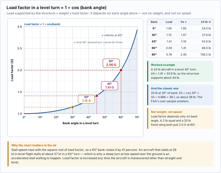
| Bank angle | Load factor (G) | Stall speed multiplier (√LF) | Interpretation |
|---|---|---|---|
| 0° | 1.00 | 1.00 | Level flight; structure carries the aircraft's weight |
| 15° | 1.04 | 1.02 | Negligible |
| 30° | 1.15 | 1.07 | Feels gentle; 15% more load than level flight |
| 45° | 1.41 | 1.19 | Load is nearly one and a half times weight |
| 60° | 2.00 | 1.41 | Double weight; stall speed is 41% higher |
| 75° | 3.86 | 1.97 | Nearly four times weight |
| 80° | 5.76 | 2.40 | The other bank angle the FAA charts always mark |
| 90° | Infinite | Infinite | A level 90° banked turn cannot be flown |
The question, near-verbatim from the FAA sample set: if an unmanned airplane weighs 33 pounds, what approximate weight would the structure support during a 30-degree banked turn while maintaining altitude? The options offered are 34, 47, and 38. Step 1 - identify what is being asked. The structure supports weight multiplied by load factor. So you need the load factor for a 30-degree level turn. Step 2 - find the load factor. Either read it off the load factor chart in the supplement at 30 degrees of bank, or compute it: load factor = 1 ÷ cos 30°. cos 30° = 0.866, so 1 ÷ 0.866 = 1.154. Step 3 - multiply by the weight. 33 × 1.154 = 38.1 pounds. Equivalently, 33 ÷ cos 30° = 33 ÷ 0.866 = 38.1. Step 4 - choose the answer. 38.1 rounds to 38 pounds. That is option C. Why the other two options are there. 34 is what you get if you assume the load increases only slightly and guess - it corresponds to a bank of about 15 degrees. 47 is what you get if you use 45 degrees of bank by mistake: 33 ÷ cos 45° = 33 ÷ 0.707 = 46.7. Both distractors are the answer to a question about a different bank angle, which is a pattern worth recognizing on the day.
The same 33-pound unmanned airplane stalls at 26 knots in level flight. It enters a 60-degree banked level turn. Step 1 - load factor. cos 60° = 0.500. Load factor = 1 ÷ 0.500 = 2.00. The structure is now supporting 33 × 2.00 = 66 pounds - double the aircraft's weight. Step 2 - stall speed. Stall speed scales with the square root of load factor. √2.00 = 1.414. Step 3 - the new stall speed. 26 × 1.414 = 36.8 knots. Reading the result. A 60-degree bank has raised the stall speed from 26 to about 37 knots - an increase of nearly 11 knots. An aircraft cruising comfortably at 32 knots is above the stall in level flight and below the stall the instant it rolls into a 60-degree turn. This is the accelerated stall, and it is why steep turns at low speed near the ground kill aircraft. Nothing about the wing changed. Only the load it was asked to carry.
Two traps live in this one calculation. First, students read the load factor chart at the wrong axis or interpolate to the wrong bank angle - the distractor answers on FAA questions are frequently the correct arithmetic for a different bank. Read the bank angle in the question twice. Second, people assume load factor depends on how heavy or how fast the aircraft is. It does not. In a level turn, load factor depends only on bank angle. A 2-pound quadcopter and a 33-pound fixed-wing both pull 2.0 G at 60 degrees of bank.
One more fact that shows up as its own question: load factor may be increased any time the aircraft is subjected to maneuvers other than straight-and-level flight. Turns, pull-ups, abrupt control inputs, and turbulence all increase it. Reducing gross weight does not increase load factor, and shifting the CG aft does not increase it either - those change other things.
Reading a manufacturer performance table
The other calculation style you may meet asks you to pull a number out of a table and adjust it. There is no trick to it beyond care: identify the row, identify the column, interpolate if you land between values, and then apply whatever correction the problem gives you.
You are flying a two-hour construction progress survey. The aircraft manual publishes hover endurance at sea level in still air: | Gross weight | Endurance | |---|---| | 8.0 lb | 28 min | | 9.0 lb | 24 min | | 10.0 lb | 20 min | | 11.0 lb (max) | 15 min | The manual adds a note: reduce endurance by 15 percent per 3,000 feet of density altitude above sea level. Your aircraft is 8.6 lb empty with battery. Your camera and mount add 0.9 lb. The site density altitude on the day is 6,000 feet. Step 1 - gross weight. 8.6 + 0.9 = 9.5 lb. Step 2 - interpolate. 9.5 lb sits halfway between the 9.0 lb row (24 min) and the 10.0 lb row (20 min). Halfway between 24 and 20 is 22 minutes. Step 3 - density altitude correction. 6,000 feet is two increments of 3,000 feet. Two reductions of 15 percent: 22 × 0.85 = 18.7, then 18.7 × 0.85 = 15.9 minutes. Step 4 - reserve. Land with 25 percent remaining: 15.9 × 0.75 = 11.9 minutes of usable flight time per battery. Step 5 - plan the mission. Each survey pass takes about 9 minutes plus 2 minutes of transit, so one pass per battery, and you need enough packs for the number of passes plus one spare. A published 28-minute aircraft has become an 11-minute aircraft, and that number - not 28 - is what goes into the flight plan. This is what 107.49(d) is asking you to do. Determine that there is enough available power for the intended operational time. It is a calculation, and it is yours.
A 20-pound unmanned airplane is flown in a level 60-degree banked turn. What load is the structure supporting?
- 20 pounds, because the aircraft weight has not changed
- 40 pounds
- 28 pounds
Answer: B. Load factor in a level turn is 1 ÷ cos(bank angle). cos 60° = 0.5, so the load factor is 2.0 and the structure supports 20 × 2.0 = 40 pounds. The 28-pound option is the answer for a 45-degree bank (20 ÷ 0.707 = 28.3), which is the classic distractor.
Beyond the test: build your own performance table for your own aircraft. Fly the same profile with the same payload three times, log the takeoff voltage, the landing voltage, the wind, the temperature, and the elapsed time, and you will have honest numbers within a month. That log is worth more than any published specification, it is what you should quote to clients when they ask what you can cover in a day, and it is the evidence you want if anyone ever asks how you determined the aircraft could complete the flight.
- The remote pilot in command, not the manufacturer, is responsible for determining the aircraft's performance, and 107.49(d) requires enough power for the intended operational time
- Manufacturer specifications are best-case laboratory figures; derate them for payload, wind, temperature, altitude, and battery age
- Load factor in a level turn = 1 ÷ cos(bank angle), and the load supported = weight × load factor
- Memorize 30° = 1.15, 45° = 1.41, 60° = 2.0, 80° = 5.76. Load factor depends only on bank angle, not on weight or speed
- The FAA's sample problem: a 33 lb unmanned airplane in a 30° level banked turn → 33 ÷ cos 30° = 38.1, so about 38 pounds
- Stall speed rises with the square root of load factor, so a 60° bank raises stall speed by about 41 percent
- Load factor increases any time the aircraft is maneuvered other than straight and level